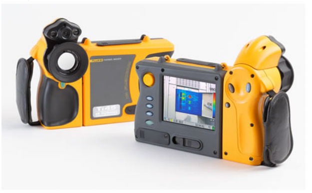
Fluke Ti40FT Infrared Camera
Fluke IR-Fusion Technology
Infrared and Visible light images are fused together - enabling you to view images in a range of modes from full IR to full visible light, and see exactly what you are viewing.
See exactly what you are viewing
Fluke IR-Fusion® technology links a real world visual image with a thermal image. It merges the two images into one, with the possibility to blend between the two images or create picture-in-picture combinations. Alarm limits can be superimposed over the visible light image to exactly pinpoint the components exceeding a specified temperature limit. Both the visual images and thermal images are available for use in reports. This speeds up documentation by reducing the need to look for individual images taken with a separate digital camera. IR Fusion helps to better identify and report suspect components and enable the repair to be done right the first time.
Large, sharp thermal images
Thanks to the largest display (five-inch) available on this type of thermal imager in combination with low-noise VOx sensors, the Fluke IR FlexCam units produce exceptionally high-quality images making even the smallest temperature differences visible. This is comparable with images normally only obtained on far more expensive instruments.
A sharp image in every situation
The innovative 180 ° articulating lens makes it possible to view and capture images in areas with poor accessibility. The display remains clearly visible while viewing over high objects, under a machine or around immoveable obstructions. The SmartFocus wheel simplifies getting a stable and sharp image. No need to take your hand off the instrument to turn a focus ring.
Make anomalies visible
Thanks to built-in functions like AutoCapture, the IR FlexCam Thermal Imagers help to troubleshoot difficult problems. The instrument is easily set up to automatically capture only those images where a temperature limit is exceeded. This way, difficult to find intermittent problems can be captured and analyzed quicker by concentrating only on the images containing the anomalies.
Analysis and reporting comes standard
The SmartView™ software (supplied with the unit) includes a complete range of infrared image viewing, analysis, annotation and reporting tools. It even allows for customized reports to accommodate specific company work processes or requirements like multiple image reporting and comparisons. To find out more select SmartView on the side navigation of this page.
Radiometric measurement – the ‘data behind the picture’
Fully radiometric thermal imagers capture and store calibrated temperature data for the matrix of thousands of points that make up a thermal image. This makes it possible to perform detailed analysis and change key parameters like emissivity or temperature range either in the field on the camera or in the office using the PC software.
Specifications | ||
Imaging performance | Thermal |
|
Field of view (FOV)* | 20 mm lens 23 ° x 17 ° FOV | |
Spatial resolution (IFOV)* | 2.60 mrad | |
Min focus distance* | 0.15 m | |
Thermal sensitivity (NETD) | ≤0.09 °C (90 mK) at 30 °C | |
Detector data acquisition / Image frequency* | 30 Hz/60 Hz | |
Focus | SmartFocus; one finger continuous focus | |
IR digital zoom | - | |
Detector type | 160 x 120 Focal Plane Array, Vanadium Oxide (VOx) Uncooled Microbolometer | |
Spectral band | 8 µm to 14 µm | |
Digital image enhancement | Automatic full-time enhanced | |
On-camera operating modes | Full thermal or full visual light. Merge thermal-visual images in SmartView software. Picture-in-Picture | |
Visible light camera | 1280 x 1024 pixels, full color | |
Visible light digital zoom | - | |
Temperature measurement | Calibrated temperature range | Ti40: -20 ˚C to 350 ˚C (-4 to 662 ºF) in 2 ranges |
Range 1 | -20 ˚C to 100 ˚C (-4 to 212 ºF) | |
Range 2 | -20 ˚C to 350 ˚C (-4 to 662 ºF) | |
Range 3 | - | |
Optional - High temperature | Ti40: - | |
Range 4 | - | |
Accuracy | ±2°C or 2 % (whichever is greater) | |
Measurement modes | Centerpoint, center box (area min/max, average) | |
Emissivity correction | 0.1 to 1.0 (0.01 increments) | |
Image presentation | Digital display | 5" large high-resolution digital display |
LCD backlight | Sunlight readable color LCD | |
Video output | RS170 EIA/NTSC or CCIR/PAL composite video | |
Palettes | Grayscale, grayscale inverted, blue red, high contrast, hot metal, ironbow, amber, amber inverted | |
Optional lenses (only available at time of original purchase) | 54 mm telephoto lens | High precision Germanium lens |
Field of view (FOV) | 9º horizontal x 6º vertical | |
Spatial resolution (IFOV) | 0.94 mrad | |
Min focus distance | 0.6 m | |
10.5 mm wide angle lens | High precision Germanium lens | |
Field of view (FOV) | 42 º horizontal x 32 º vertical | |
Spatial resolution (IFOV) | 4.9 mrad | |
Min focus distance | 0.3 m | |
Image and data storage | Storage medium | Compact flash card stores over 1000 IR images (1 GB card standard) |
File formats supported | 14 bit measurement data included. Exportable JPEG, BMP, PNG, GIF, TIFF. | |
Interfaces and software | Interface | Compact flash card reader included |
Software | SmartView; full analysis and reporting software included | |
Laser | Classification | Class II |
Laser targeting | Laser dot visible on screen when blending thermal and visible image | |
Controls and adjustments | Set-up controls | Date/time, temperature units C/F, language, scale, LCD intensity (high/normal/low) |
Image controls | Level, span, auto adjust (continuous/manual) | |
On-screen indicators | Battery status, target emissivity, background temperature and real time clock | |
Power, battery life | Battery type | Li-Ion smart battery, rechargeable, field-replaceable |
Battery operating time | 3 hours continuous operation (2 hours with IR-Fusion engaged) | |
Battery charging | 2 bay intelligent charger powered via AC outlet | |
AC operation | AC adapter 110/220 VAC, 50/60 Hz (Ti45 only) | |
Power saving | Automatic shutdown and sleep modes (user specified) | |
Environmental and mechanical design | Operating temperature | -10 °C to +50 °C (14 °F to 122 °F) |
Storage temperature | -40 °C to +70 °C (-40 °F to 158 °F) | |
Relative humidity | Operating and storage 10% to 95%, non-condensing | |
Water and dust resistant | IP54 | |
Weight (including batteries) | 1.95 kg (4.3 lbs) | |
Camera size (HxWxD) | 162 x 262 x 101 mm (6.5" x 10.5" x 4.0") | |
Application of thermal cameras |
|
Application samples
Connection of substations
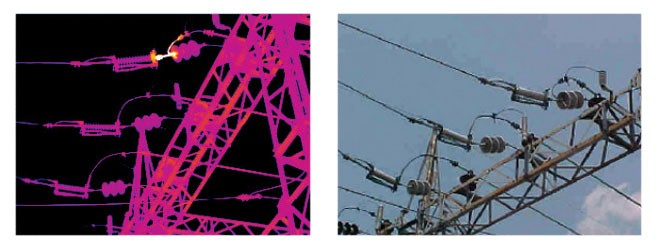
This infrared image shows the "hot" connection (measured using a telescopic lens junction temperature is 225 ° C) in the substation, which feeds power to the hospital and the surrounding her building. Using a thermal imager could immediately fix the defect. The electrical connection has been damaged during a lightning storm, causing the contact to re-welded to the support bracket of the insulator.
Circuit breaker
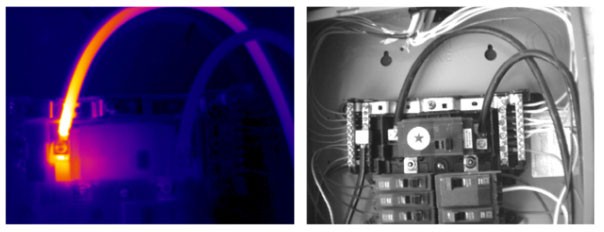
Fuse
Overheating in the place of contact of the fuse
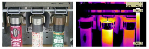
Switch 110 A
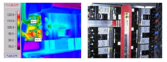
Switch 240V 110A is used in the LAN system power. The load distribution in phases: A = 65 B = 95 N = 84. Current load for phase B is greater than 80% and the temperature is greater than the nominal value for the switch.
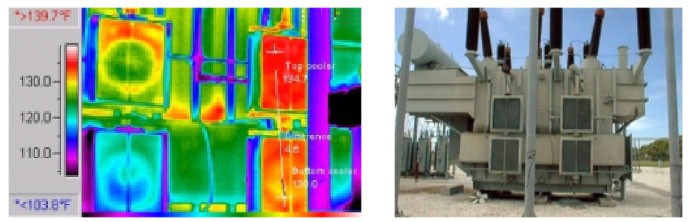
Transformer
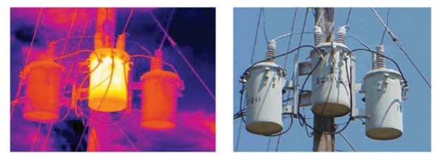
Allocation of excess heat in the distribution transformer was due to the emergence of internal defects and low oil level.
Transformer
Cold cooling ribs due to low oil level in the transformer.
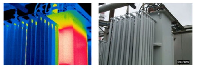
Transformer radiators
This thermal image shows a cold radiator (bottom left). Perhaps this is due to a faulty pump. Such a situation can be a serious problem, since this reduces transformer efficiency.
Motor
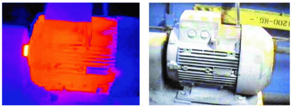
The problem with a winding.